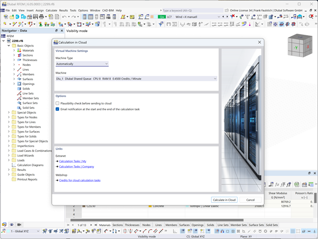
The model and loads are entered as usual in the RFEM interface.
You can start the cloud calculation by selecting an entry in the Calculate menu. Then, select the virtual machine suitable for the task and start the calculation.
After the start, the image is used to create a virtual machine on which the computing server is started. This takes over the calculation of your file.
You can monitor the processing of calculation tasks in the Extranet.

Would you like to create a cross-section from the import of a DXF file? It's very easy. You have the following options:
- Create elements automatically
- Use DXF template lines as centerlines of elements with a defined thickness
Do you select the option to create the elements automatically? In that case, the program creates the elements and the associated parts for you from the contour of the outline. It only creates the elements not exceeding a definable maximum thickness.
Your cross-section geometry is available as a centroidal axis model? Then use DXF template lines as centerlines of elements with a defined thickness. Defining a thickness that is assigned equally to all elements.
Do you miss the "Create elements automatically" and "Create elements on lines" functions? Don't worry, both are also available in the "Edit" menu under "Manipulation".
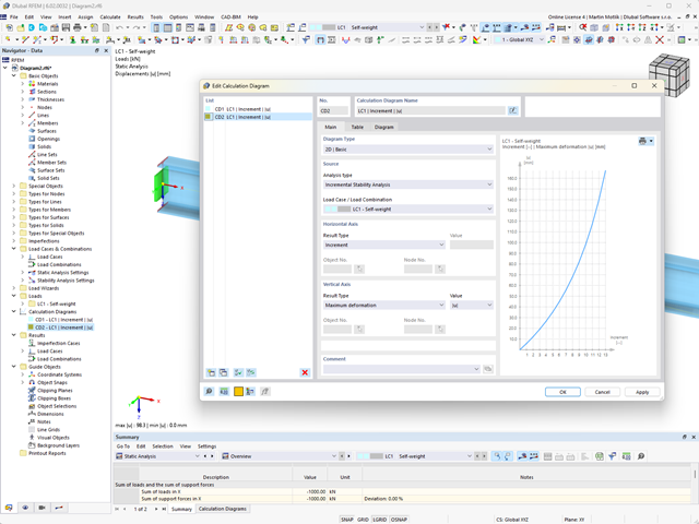
Do you want to create calculation diagrams? With RFEM and RSTAB, this works globally and without any problems. Create and organize your calculation diagrams directly in the Navigator - Data or via the menu Insert → Calculation Diagrams.
Use calculation diagrams to record and display a relation between the various calculation results.
It is also possible to superimpose similar diagrams.
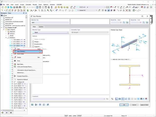
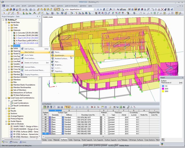
You create your models in the graphical user interface typical for CAD programs. By right-clicking the graphical or navigator objects, you activate a shortcut menu that you can use to select and modify the objects.
The operation of the user interface is intuitive, as you will notice soon. Therefore, you can create the structural and loading objects in a minimum amount of time.
Go to Explanatory Video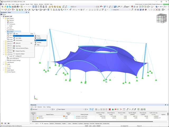
A great strength of the Dlubal programs is their intuitive, easy-to-learn operation. RFEM 6 is no exception. Create your structure in a user interface usual for CAD or via tables. By right-clicking the graphical or navigator objects, a shortcut menu appears, which facilitates you creating or editing the objects. Due to the intuitive user interface, you can create structural and loading objects in a very short time.
Go to Explanatory Video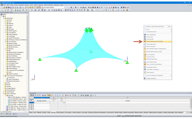
Activating 'Show Form-Finding' in the shortcut menu leads to an automatic preliminary form-finding according to the saved form-finding properties when you change the structure of membrane surfaces. This interactive graphics mode is based on the force density method.
More Information FAQ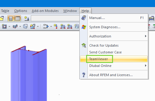
It is possible to access the TeamViewer directly by opening the Help menu of RFEM and RSTAB. Customers with Service Contract Pro can thus benefit from easy and quick online support via video conference.
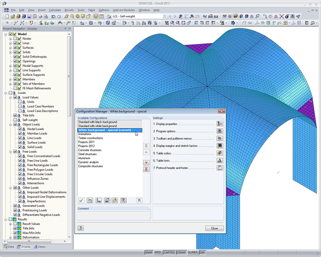
If you are interested in making your daily work easier and more efficient, you should also pay attention to this feature. Program configuration menus and toolbars can be freely customized. This allows you to arrange your frequently used functions in a user-defined way and save time. Everything from the beginning? No problem: You can restore the default settings of the program with a mouse click. Tables, navigators, and toolbars can also be moved and docked as required.
Furthermore, you can use the configuration manager to set the graphic display properties, toolbars, and so on in a user-defined way and save them as your own configuration. Thus, the software becomes your individual productivity enhancer.
The Dlubal programs are user-friendly. This way, you will have a short induction period and easy handling of the software.
Your structure is created in a user interface usual for CAD or via tables. By right-clicking the graphical or navigator objects, you can activate a shortcut menu that allows you to easily create or modify the objects. Try it out for yourself and let yourself be inspired by the intuitive user interface! Therefore, you can create the structural and loading objects in a minimum amount of time.
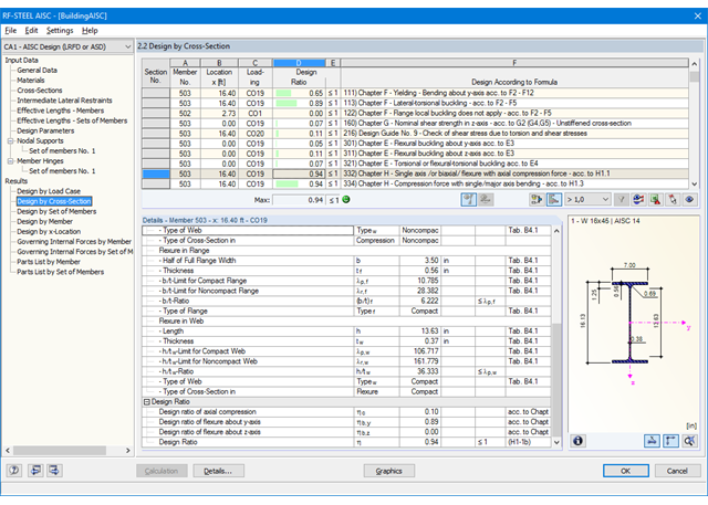
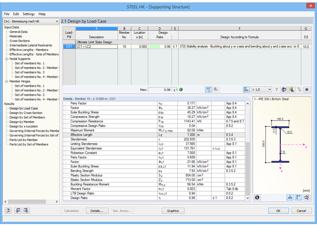
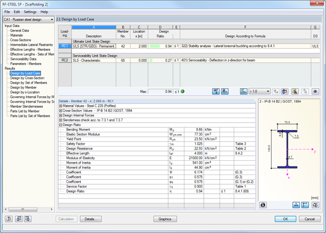
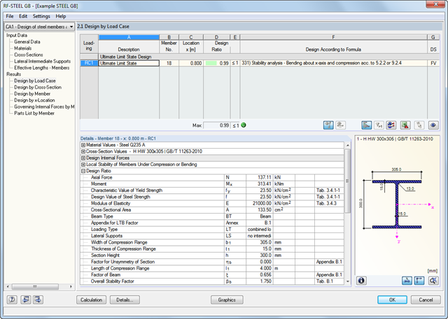
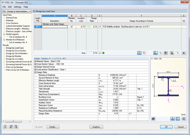
The first result window shows the maximum design ratios with the corresponding design of each designed load case, load combination, or result combination.
The other result windows list all detailed results sorted by specific subject in extendable tree menus. All intermediate results along the members can be displayed at any location. In this way, you can easily retrace how the module has performed the individual designs.
The complete module data are part of the RFEM/RSTAB printout report. You can select the report contents and extent specifically for the individual designs.
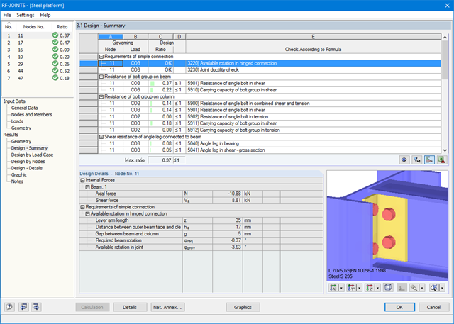
The result windows list all results of the calculation in detail. In addition, 3D graphics are created, where individual components as well as dimension lines and, for example, This allows you, for example, to display or hide the weld data. The summary shows if the individual designs have been fulfilled: The design ratio is additionally visualized with a green data bar, which turns red when the design is not fulfilled. Furthermore, the node number and the governing LC/CO/RC are displayed.
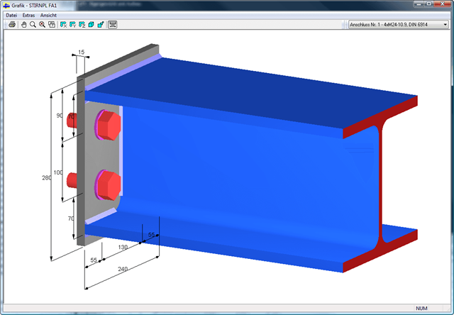
When selecting a design, the module shows the detailed intermediate results including the actions and the additional internal forces from the connection geometry. There is the option to display the results by load case and by node. The connections are represented in a realistic 3D rendering possible to scale. In addition to the main views, it is possible to show the graphics from any perspective.
You can add the graphics with dimensions and labels to the RFEM/RSTAB printout or export them as DXF. The printout report includes all input and result data prepared for test engineers. It is possible to export all tables to MS Excel or in a CSV file. A special transfer menu defines all specifications required for the export.
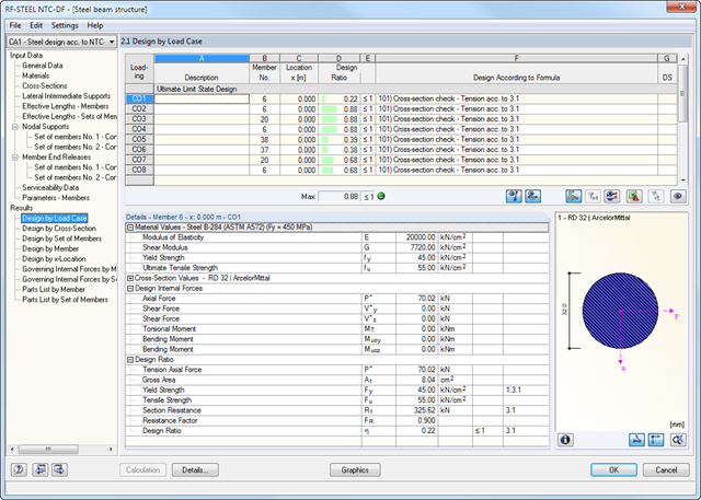
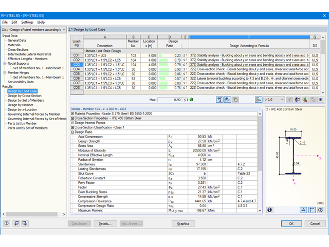
The first results window shows the maximum design ratios with the corresponding design of each designed load case, load combination, or result combination.
The other result windows list all detailed results sorted by specific subject in extendable tree menus. All intermediate results along a member can be displayed at any location. In this way, you can easily retrace how the module has performed the individual designs.
The complete data from the module are part of the RFEM/RSTAB printout report.
All design results and design checks are displayed in detail and in a comprehensible manner. An error log indicates non-designable situations or failed recommendations. Due to the permanent integration in RFEM/RSTAB, subsequent modifications in the structural system and in loading are automatically taken into account for the connections to be checked.
If one of the designs could not be fulfilled, the corresponding line is highlighted in red. The output appears in a short or a long form in the global printout report of RFEM/RSTAB. Furthermore, you can easily export all result tables to MS Excel or in a CSV file. A special transfer menu defines all specifications required for the export.
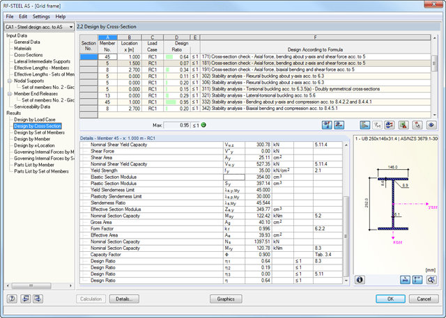
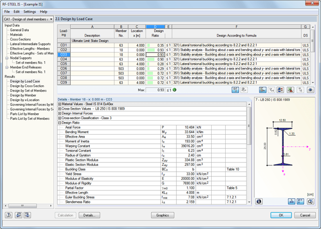
The first window shows the maximum design ratios including the corresponding design of each designed load case, load combination, or result combination.
The other result windows list all detailed results sorted by specific subject in extendable tree menus. All intermediate results along the members can be displayed at any location. In this way, you can easily retrace how the module has performed the individual designs.
The complete module data are part of the RFEM/RSTAB printout report. You can select the report contents and extent specifically for the individual designs.
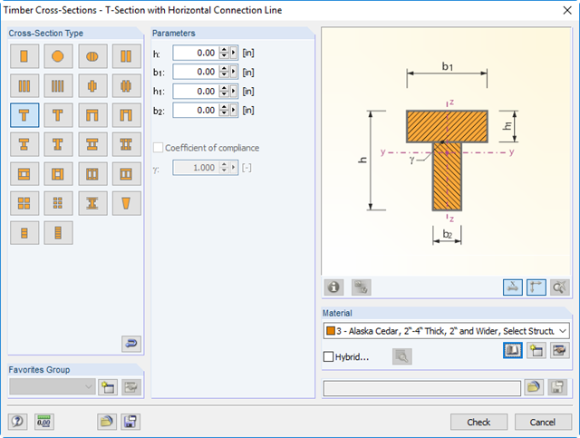
You can define built-up timber cross-sections, for example, channel, T, I, and box girders. Single elements are connected by rigid or semi‑rigid connections. Furthermore, hybrid cross-sections are available. In this case, a submenu provides an option to assign different materials to the individual cross‑section parts.
The first window shows the maximum design ratios including the corresponding design of each designed load case, load combination, or result combination.
The other result windows list all detailed results sorted by specific subject in extendable tree menus. All intermediate results along the members can be displayed at any location. In this way, you can easily retrace how the module has performed the individual designs.
The complete module data are part of the RFEM/RSTAB printout report. You can select the report contents and extent specifically for the individual designs.
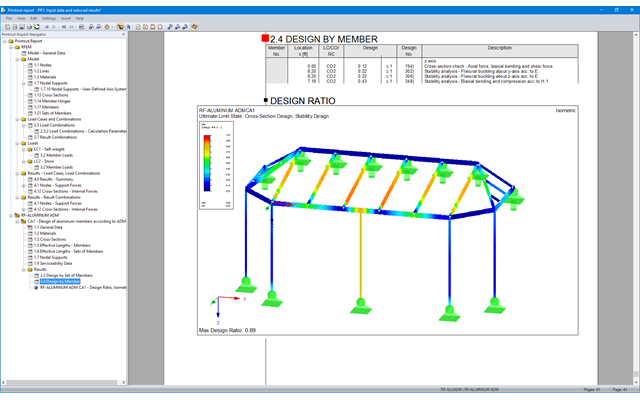
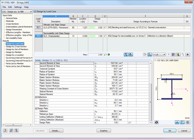
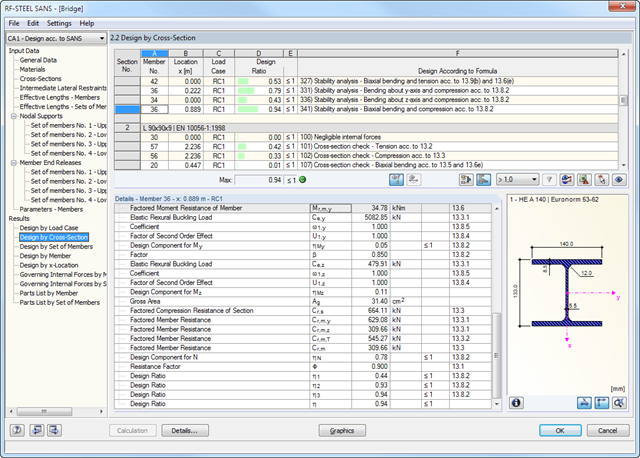
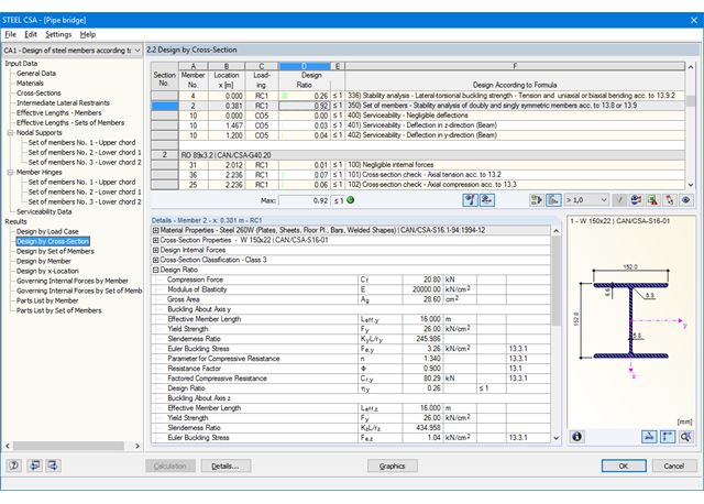
After the design, the results are displayed in different windows sorted by cross-sections, members, sets of members, or x-locations. The corresponding cross-section graphic is always displayed with the result values in tables. In RFEM/RSTAB, they are highlighted by different colors in the structural model. Critical or oversized components can be identified at a glance. You can modify the colors and values assigned.
Result diagrams of a member or a set of members ensure targeted evaluation. It is also possible to represent all intermediate values.
The masses determined during the design are displayed in parts lists for both members and sets of members.
Furthermore, you can export all result tables to MS Excel or in a CSV file. A special transfer menu defines all specifications required for the export.
The first window shows the maximum design ratios including the corresponding design of each designed load case, load combination, or result combination.
The other result windows list all detailed results sorted by specific subject in extendable tree menus. All intermediate results along the members can be displayed at any location. In this way, you can easily retrace how the module has performed the individual designs.
The complete module data are part of the RFEM/RSTAB printout report. You can select the report contents and extent specifically for the individual designs.
The first result window shows the maximum design ratios including the corresponding design of each designed load case (load combination / result combination).
The other result windows list all detailed results sorted by specific subject in extendable tree menus. All intermediate results along a member can be displayed at any location. In this way, you can easily retrace how the module has performed the individual designs.
The complete module data are part of the RFEM/RSTAB printout report. You can select the report contents and extent specifically for the individual designs.
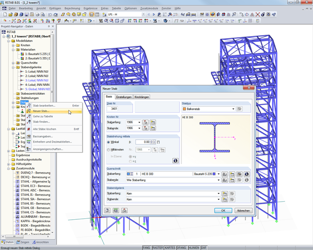
Models are created in the graphical user interface typical for CAD programs. By right-clicking the graphical or navigator objects, a shortcut menu appears, which facilitates creating or editing the objects.
The user interface is intuitive to use. Therefore, the model and loading objects can be created in a minimal amount of time.
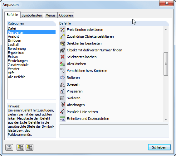
Program configuration menus and toolbars can be freely customized. It is possible to setup an arrangement of frequently used functions and tools for quick access. Tables, navigators, and toolbars can also be freely moved and docked. The default settings of the program can be restored at the click of a button.
In addition, it is possible in the Configuration Manager to set the graphic display properties, toolbars, and so on in a user-defined way and save them as your own configuration.
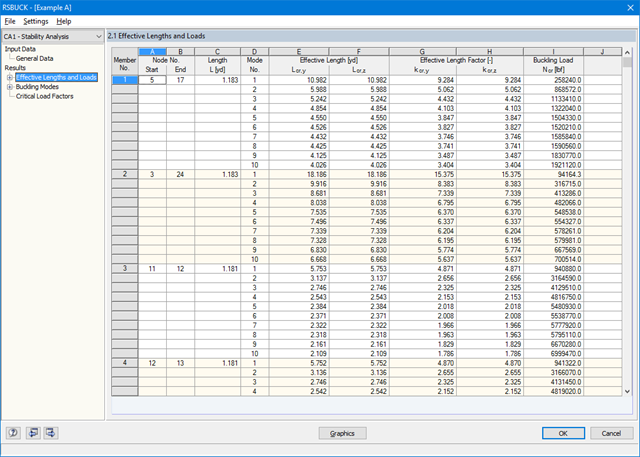
The results of the buckling analysis are displayed in clearly arranged result tables and graphics. Since RSBUCK is fully integrated in RSTAB, you can adjust all results in detail in the printout report according to your individual requirements.
Furthermore, you can easily export all result tables to MS Excel or in a CSV file. A special transfer menu defines all specifications required for the export.
For reasons of result evaluation, clearly arranged result tables are available. The first window shows the maximum design ratios including the corresponding design of each designed load case, load combination, or result combination.
The other result windows list all detailed results sorted by specific subject in extendable tree menus. All intermediate results along the members can be displayed at any location. In this way, you can easily retrace how the module has performed the individual designs.
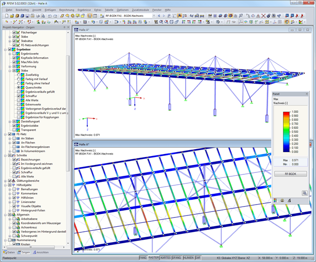
The complete module data are part of the RFEM/RSTAB printout report. You can select the report contents and extent specifically for the individual designs. The graphical result display of the governing design criteria in RFEM/RSTAB provides a quick overview of the design ratios of individual structural components.